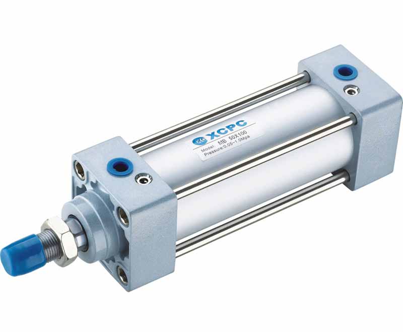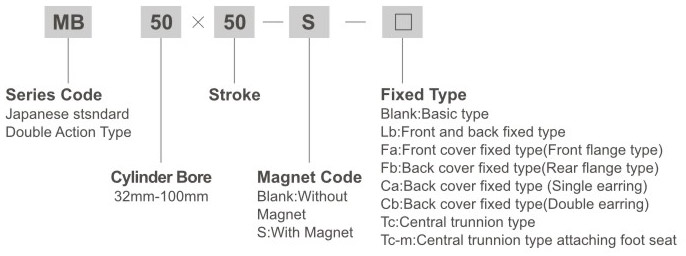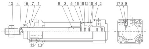
MB Series Standard Cylinder

|
Cylinder diameter |
32 |
40 |
50 |
63 |
80 |
100 |
|
Working Medium |
Air |
|||||
|
Action type |
Double acting |
|||||
|
Proof pressure |
15.3kgf/cm2(1.5Mpa) |
|||||
|
Max.pressure |
10.2kgf/cm2(1.0Mpa) |
|||||
|
Min.pressure |
0.5kgf/cm2(0.05Mpa) |
|||||
|
Environment and fluid temp |
-10~+60℃ |
|||||
|
Piston veocity |
50~1000mm/s |
|||||
|
Buffering |
Air buffering |
|||||
|
Stroke tolerance |
~0~250+10 , 251~1000+14 , 1001~1500+18 |
|||||
|
Rc(PT)Joint size |
G1/8" |
G1/4" |
G3/8" |
G1/2" |
||
|
Bore(mm) |
Standard Stroke |
|
32 |
25,50,75,100,125,150,175,200, 250,300,350,400,450,500 |
|
40 |
25,50,75,100,125,150,175,200, 250,300,350,400,450,500 |
|
50 |
25,50,75,100,125,150,175,200, 250,300,350,400,450,500,600 |
|
63 |
25,50,75,100,125,150,175,200, 250,300,350,400,450,500,600 |
|
80 |
25,50,75,100,125,150,175,200, 250,300,350,400,450,500,600,700,750 |
|
100 |
25,50,75,100,125,150,175,200, 250,300,350,400,450,500,600,700,750 |

|
Diameter |
Stroke range |
Thread length available |
A |
□B |
□C |
φD |
φE |
F |
G |
MA |
MB |
J |
K |
MM |
N |
P |
S |
V |
W |
H |
ZZ |
|
32 |
~500 |
19.5 |
22 |
46 |
32.5 |
12 |
30 |
13 |
13 |
16 |
4 |
M6×1.0 |
6 |
M10×1.25 |
27 |
1/8 |
84 |
4 |
6.5 |
47 |
135 |
|
40 |
~500 |
27 |
30 |
52 |
38 |
16 |
35 |
13 |
14 |
16 |
4 |
M6×1.0 |
6 |
M14×1.5 |
27 |
1/4 |
84 |
4 |
9 |
51 |
139 |
|
50 |
~600 |
32 |
35 |
65 |
46.5 |
20 |
40 |
14 |
15.5 |
16 |
5 |
M8×1.25 |
7 |
M18×1.5 |
31.5 |
1/4 |
94 |
5 |
10.5 |
58 |
156 |
|
63 |
~600 |
32 |
35 |
75 |
56.5 |
20 |
45 |
14 |
16.5 |
16 |
5 |
M8×1.25 |
7 |
M18×1.5 |
31.5 |
3/8 |
94 |
9 |
12 |
58 |
156 |
|
80 |
~750 |
37 |
40 |
95 |
72 |
25 |
45 |
20 |
19 |
16 |
5 |
M10×1.5 |
10 |
M22×1.5 |
38 |
3/8 |
114 |
11.5 |
14 |
72 |
190 |
|
100 |
~750 |
37 |
40 |
114 |
89 |
30 |
55 |
20 |
19 |
16 |
5 |
M10×1.5 |
10 |
M26×1.5 |
38 |
1/2 |
114 |
17 |
15 |
72 |
190 |

|
|
|
|
|
